| |
|
Sample CBD-application ‘City-GIS’
|
|
|
The software components that are equivalent to the physical components and can enable the CBD-process and achieve the CBD-structure are referred to as right kind of components. Having been created hundreds of right kind of software components and component-hierarchies over a decade, I can prove that it is possible to build executable of almost any large and complex software-product comprising the CBD-structure (if given an opportunity). This section provides a sample software application created by hierarchically assembling such right kind of software-components.
|
|
|
Assume you were asked to create geographical information system for a city (e.g. City_GIS application). It must be highly scalable and many times more agile to accommodate evolving needs (customer said he don’t yet know needs of target users, he is new to domain, so will frequently change his mind/requirements as he learns/experiment during the process). Therefore, you must be able to refine each of the component little by little autonomously as your team learns evolving needs, technologies and your team gains more insights or expertise of user/market needs).
|
|
|
Let’s assume in first release, it must display three SCCs (Self-Contained Components) that are: (i) City map and real-time traffic conditions (ii) Important landmarks and (iii) Real-time Air Traffic over the city map. You may ask 3 developers A, B and C to develop the 3 RCCs (Replaceable-component classes) respectively for assembling the 3 RSCC (Replaceable Self-Contained Component objects) respectively. Building each RCC for each of the 3-SCCs is not that much different from building and testing an independent application. For example, implement whole custom application code for each SCC in an application and encapsulate the SCC-code in a class called RCC.
|
|
1
|
Ask developer-A to build City map containing streets and real-time traffic as a RCC (e.g. CityStreetMap_RCC),
|
|
2
|
Ask developer-B to build landmarks as a RCC (e.g. Java class CityLandmarks_RCC), and
|
|
3
|
Ask developer-C to build Air Traffic Monitor as a RCC (e.g. Java class named CityATC_RCC)
|
|
|
|
Where, developer-A can design and develop a GUI-application independently to display city-map containing streets, lakes, canals, rail-tracks and city-blocks etc. The application also displays real-time traffic conditions on the map. To make this application a RCC, developer-A must encapsulate most of the custom application for the SCC in a class-definition. Likewise, developer-B and developer-C can develop each of the components (e.g. SCCs) as an independent application respectively and must encapsulate most of the code implemented for the component/SCC in each application in a class definition to make each SCC a Replaceable-SCC.
|
|
|
Listing-1
|
- Void CGM(Out) { // CGM of City_GIS_RCC
ASSEMBLES the components
-
- // Include replaceable component created by developer "A"
- RepComp CityMap = new CityMap_RCC (ACi,ZipCode);
- this.canvas.AddChild (CityMap, 0, 0, null);
-
- // Include replaceable component created by developer "B"
- RepComp LandMarks = new CityLandmarks_RCC(ACi, ZipCode);
- this.canvas.AddChild (LandMarks, 0, 0, null);
-
- // Include replaceable component created by developer "C"
- RepComp AirTraffic= new CityATC_RCC(ACi, AirportCode);
- this.canvas.AddChild (AirTraffic, 0, 0, null);
-
- this.canvas.CGM(Out); // Display the GIS for City
- }
|
|
|
Each developer can have highest degree of autonomy from other developers to build class (or RCC) for his component (or SCC), where the RCC makes the SCC replaceable (i.e. it is easy to disassemble and to re-assemble). He could work closely with user to custom-build/redesign (fix-and-test in step-1 of CBD-process) his RCC/RSCC satisfies current unique needs of the end user. Each RCC for each SCC is custom designed in the context of this specific application and in the context of all other SCCs/parts of the application that collaborate with this SCC.
|
|
|
One can assemble each of the RSCCs by writing just 2 lines of code, where one line to instantiate an object instance of the RCC and another line to attach the RSCC to it’s container-RSCC as shown in code listing-1 (where each of the SCC can also be disassembled by deleting the same 2 lines of code, hence it is a Replaceable-SCC). Each RCC/SCC can be tested independently outside by implementing a test application that includes an object instance of just the RCC as illustrated in listing-1 (i.e. just assemble one RSCC instead of all 3 RSCCs).
|
|
|
Listing-2
|
- Void CGM(Out) { // CGM of CityLandmarksCF created by developer-B
- RepComp Hotels = new CityHotels_RCC (ACi,ZipCode);
- this.canvas.AddChild (Hotels, 0, 0, null);
-
- RepComp Theatres=new CityTheaters_RCC(ACi, ZipCode);
- this.canvas.AddChild (Theatres, 0, 0, null);
-
- RepComp TouristSpots
= new TouristSpots_RCC(ACi, ZipCode);
- this.canvas.AddChild (TouristSpots, 0, 0, null);
-
- this.canvas.CGM(Out); // Display landmarks for City
- } // This ASSEMBLES the subcomponents for the CityLandmarks_RCC
|
|
|
It is extremely important and essential that each of the RCC must be developed as an independent application and one must be able to test each RCC autonomously (e.g. by implementing generic test application). If developer-B feels RCC for landmarks is too complex, he can subdivide that in to 3 sub-RCCs: (i) Hotels (ii) Theaters, (iii) Tourist spots. Each landmark must display a popup window on mouse-over, which must present detailed real-time information about the landmark. He may ask 3 developers B1, B2 and B3, to build/test below 3-RCCs independently:
|
|
1
|
Ask B1 to build Important Hotels as a RCC
|
|
2
|
Ask B2 to build Theaters as a RCC, and
|
|
3
|
Ask B3 to build Tourist Spots as a RCC
|
|
|
|
When classes for each of the above SCCs are built and tested (by developers B1, B2 and B3), each of the RSCC can be assembled (or dissembled) by including (or deleting) just 2 lines of code as shown in listing-2, which assembles the sub-RSCCs for implementing a container RCC for building a container RSCC by using CityLandmarks_RCC.
|
|
|
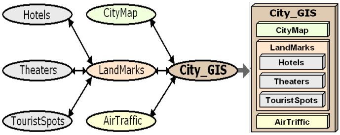
FIG-1: A replaceable component - either it is a container component (e.g. LandMarks or City_GIS) or a subcomponent (e.g. Hotels, Theaters or AirTraffic) can be disassembled (or completely removed from the application) by removing about 2 to 5 lines of code.
|
|
|
|
It is
extremely important to notice that: Each container component
not only physically encapsulates all its subcomponents (hence, removing container component effectively removes all its
subcomponents without leaving any traces of the subcomponents); but also preserves the replaceable property of each of its subcomponents
(i.e. each of the subcomponents can be disassembled by removing about 2 to 5 lines of code).
|
|
|
|
Any replaceable-SCC that is either a container-SCC (e.g. LandMarks or City_GIS) or a sub-SCC (e.g. Hotels, Theaters or AirTraffic) can be disassembled (or removed from the application) by removing 2 or 3 lines of code (e.g. listing-1). Please notice: container-SCC logically encapsulates all its sub-SCC. That is, removing container-SCC (e.g. Landmarks) from listing-1 (deleting lined 7-9) effectively removes all its sub-SCC, without leaving any traces of its sub-SCCs (e.g. Hotels, Theaters & TouristSpots) form the application. This component-hierarchy also preserves the replaceable property of each of its sub-SCCs (i.e. each sub-SCC such as Hotels can be removed as a unit by removing 2 lines of code in listing-2).
|
|
|
Now you presented City_GIS application to the city mayor and he is impressed. But he asked you to also include city emergency response (ER) as well (which are required to show the locations of moving ambulances & fire-engines on the City-map). You ask developer-D to implement the ER as a RCC. Each RCC can be implemented and tested autonomously. Once fully tested, it must require no more than 2 lines to assemble (or disassemble) the CP into the container City_GIS_RCC:
|
|
|
1. RepComp ER =new Ambulances(ACi, Zip);
|
|
2. this.canvas.AddChild(ER, X_location,Y_location, null);
|
|
|
Inserting the above code at line number-10 in listing-1 effectively assemble Emergency Response SCC into the City-GIS application. If you create the Geographical Information System (GIS) as a RCC, you could display GIS information system of many cities in a container-TAB. It may display respective city-names as Titles of TABs. Selecting a Title/Tab, displays GIS for the City. The container-TAB can be implemented in a RCC to use as sub-component in another container-component, and so on. This kind of component-hierarchy can go on forever (i.e. building larger and larger container-components).
|
|
|
For example, if City_GIS application required adding a CityWeatherMap, then a RCC can be implemented independently to present CityWeatherMap. An RCC by name CityWeather_RCC can be custom designed to satisfy unique needs of the users of City_GIS application. Also CityWeather_RCC must be designed in the context of City_GIS application, for example, take application context into consideration, such as the size of the City-map, co-ordinate system and scaling to properly overlay CityWeather over the City-map of City_GIS application.
|
|
|
Each RCC must require no more than 2-3 lines to assemble its SCC, so all construction and configuration code must be implemented inside the RCC. Also it is possible to save all the files containing custom application specific code implemented for the RCC to present CityWeather in a folder, for example, in order to track and preserve the autonomy for the code base for CityWeather_RCC. This autonomous code base (of RCC is equivalent to a blueprint of physical-component) can be used to refine or redesign the RCC to satisfy future evolving needs (step-3 of CBD-process). Even during initial implementation, it is often necessary to refine the RCC to satisfy unique needs of diverse users of custom application. For example, users might suggest changes, when first working WeartherMap_RCC is shown to them for feedback or even your designers may find shortcomings.
|
|
|
Important Note-1: Often one must implement hundreds of lines of custom application code to add each such large SCC to an application. Each of the software-component is encapsulated in a RCC, (an exclusive set of files contains source code of the RCC, where the files don’t contain source code of any other components). If each SCC is not encapsulated in a class-definition (i.e. RCC), the source code of the SCC ends up spread across many non-exclusive files, where each of the files also contain code-sections of other SCCs. To redesign a SCC, one must change the code carefully without effecting code of other SCCs in the many-files. It is not possible to test the SCC away from the application to assure its quality separately. If source code of a SCC is spread across many non-exclusive files, it requires considerable effort to locate and remove the source code from multiple files to remove the SCC.
|
|
|
In this example, the coupling interfaces of the RSCC for WeatherMap are custom designed in the context of City_GIS application and other RSCCs in City_GIC application that need to communicate with the RSCC for WeatherMap. For example, if RSCC for City_ATC (Air Traffic Control) needs a service from WeatherMap_RCC, then it is required to pre-define a coupling interface to allow communication between the two RSCCs. The RCC for WeatherMap can implement a service-function to provide the service and RCC for City_ATC can be designed to use the interface for requesting the service.
|
|
|
The container application implements communication code to allow collaboration between the RSCCs. If the coupling interface of a service-providing RSCC and interface of a service-consuming RSCC is pre-defined and designed to compliment each other, then communication code implemented in the code of the container application can be minimized (e.g. by directly input the service-reference to a service function or object of the service-providing RSCC’s into the service-consuming RSCC, as shown in the pseudo-code example below). For example, to provide a service the service-providing RSCC implements a service-function that can be called to request the service of the service-providing RSCC. In this case, description for the service-interface comprises information regarding type of parameters and order of parameters for the service-function. A service-consuming RSCC may be designed to call the service-function to request the service, wherein the parameters of the service-function are used for data exchange between the two collaborating RSCCs.
|
|
|
1. City_ATC_RC.SetWeatherService(WeatherMap_RC.WeatherService);
|
|
|
In the above example, the coupling-interface for City_ATC_RCC is implemented in the context of the coupling-interface of the WeatherMap_RCC, so it is possible to directly input the service function of WeatherMap into City_ATC as shown above. When the collaborating RSCCs implemented in the context of a specific application and each coupling-interface in the context of other RSCCs or parts that use on coupling-interface, it requires no more that two lines for assembling each RSCC. Also it may require no more than one line of communication code for creating each coupling between any two collaborating components. However in many cases it is desirable to eliminate even this one line of manual communication code for each coupling, so that it requires no more that 2 to 3 lines to include and assemble each RSCC. The flowing tool presents not only a mechanism to eliminate the need for such communication code but also to validate and mange the coupling-interfaces.
|
| |
|
Ideal CBSD for each large software application must satisfy the 5-Rules
|
|
The CBD-process requires identifying each of the SCC (Self-Contained Components) in a software application and implementing an RCC for each SCC, so that it requires no more than 2 to 5 lines to assemble the SCC.
An Ideal CBD-application should strive to satisfy following rules:
|
|
1
|
The developers of each SCC start designing and developing each custom RCC individually.
|
|
2
|
Once very simple versions (e.g. initial bare-place-holders) of RCCs are ready, engineers build an ideal CBD application by taking a bare generic application template and start assembling each of the components, where no component requires more than 2 to 5 lines to
assemble.
|
|
3
|
Any component (i.e. replaceable-SCC or RSCC) can be disassembled by removing the 3 to 5 lines; and Removing all of the components
one RSCC at a time must end up with the above original generic or reusable application template.
|
|
4
|
Developer of each RCC can continue to refine or redesign his SCC (i.e. component) little-by-little individually and test it independently to make it
as best as it can be.
(i.e. Each RCC is individually evolved from initial/dummy-place-holder state to the state where it
is released).
|
|
5
|
The above rule-3 and rule-4 must be true (a) during and even after release of the first version
(i.e. step-1 of CBD-process) and
(b) during and after release
of each of the future version (i.e. step-3 of CBD-process) of the software
product (as illustrated by FIG-3 below).
|
|
|
It is possible to invent sophisticated CASE-tools to eliminate the need for implementing any communication code for coupling each of the components in the application, so that each RSCC can be included in the application by properly including just an object instance of its RCC. The Real-CBD can and must use
sophisticated CASE-tools for not only (a) creating couplings between the components in the application automatically (without any need for implementing communications code in the application), but also (b) manage the coupling interfaces, for example to detect any broken or mismatched couplings between any two components.
|
|
|
|
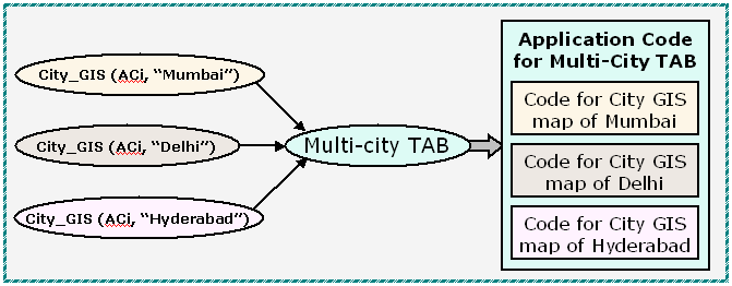
If you create the Geographical information system (GIS) as a replaceable component class, you could display GIS information system of many cities in a TAB, as shown
below. The TAB displays the city names as TAB Titles. Selecting a Title display GIS for the City.
|
|
- Void CGM(Out) { // CGM for MyTab_RCC for three cities
-
- RepComp Delhi = new
City_GIS_RCC(ACi,
"Delhi", AirPortCode);
- RepComp Hyd
= new City_GIS_RCC(ACi, "Hyderabad",
AirPortCode);
- RepComp Mumbai
= new City_GIS_RCC(ACi, "Mumbai",
AirPortCode);
-
- RepComp RSCC_Array[] = new {Delhi,
Hyd, Mumbai};
- String Titles[] = {"Delhi",
"Hyderabad", "Mumbai"};
-
- MyTab = new TAB_Comp(ACi,
RSCC_Array, Names);
- MyTab . CGM(Out); // Display in a TAB Component
- }
|
|
FIG-2
|
| |
|
It is absolutely essential for the software designer of large applications to discover the innate nature and essential property (e.g. referred to as Self-Contained) universally shared by any large functional physical components. This discovery and knowledge helps him to identify multiple large SCCs (Self-Contained Components) in each large application, where construction code that must be implemented for each SCC can be encapsulated in a RCC (Replaceable Component Class). Then each RCC can be evolved as an independent application.
|
|
|
The software products are uniquely different from physical products. For example, if a person purchases a Camry, he won’t ask Toyota
company that the car must be evolved into a Lexus within few years by refining each of the components
little-by-little (every few months). But the customers (e.g. JP Morgan, AIG, Exxon or
Wal-Mart) of software outsourcing vendors (e.g. IBM, Infosys or Wipro) expect
the first release version of a complex software product must be frequently refined little-by-little
(every few months) and must be evolved substantially overtime.
|
|
FIG-3: Please refer to
FIG-4 below to see a sample component hierarchy
|
|
|
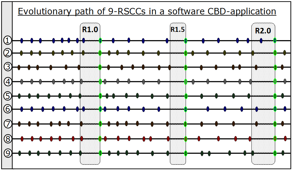
Although a large application may have hundreds of RCCS, the above figure shows evolutionary paths of 9 RCCs in an application.
The code base for each RCC is
sandboxed and can be independently versioned. In the figure, each node in the path of each RCC is an intermediate test-point, for example, to show to stakeholder for getting feedback or to test updated coupling interfaces. The developer of each RCC can continuously refine his component ‘little-by-little’, which can be a continuous uninterrupted process, and only pauses for each major release of the application, where the pausing period for each release is shown in
the shaded boxes. The green nodes indicate the final version used for the
release, which is also the starting point for resuming the 'little-by-little'
improvements for intermediate patches and for next release.
|
|
|
|
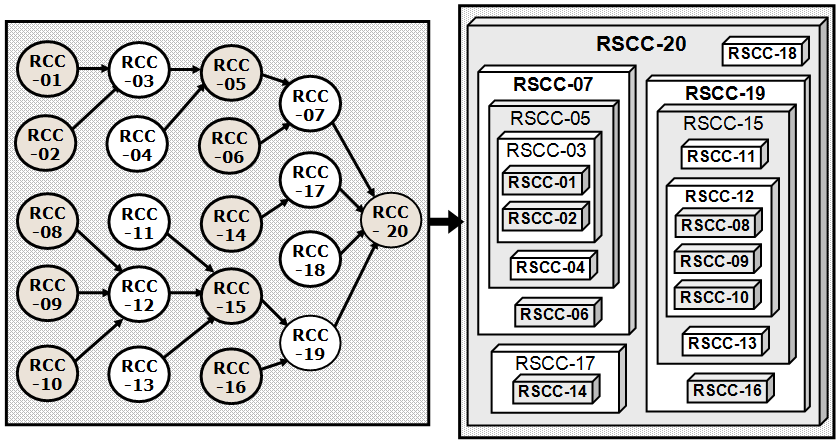
FIG-4: The abive figure shows component hierarchy, where each
RCC (e.g. RCC-15) is used (by RCC-19) to assemble a RSCC (e.g. RSCC-15 as a sub-component of RSCC-19). For example, RCC-15 uses RCC-11, RCC-12 and RCC-13 to
assemble its sub-components RSCC-11, RSCC-12 and RSCC-13 respectively. In case
of an ideal CBSD, no RCC requires more than 3 to 5 lines to assembly
respective RSCC, where an intelligent CASE-tool
can be used to create & manage
communication code & interfaces for allowing collaboration between the RSCCs
in RSCC-20.
|
|