Figures
to Introduce Component Factory & Loosely Coupled component paradigm
|
The loosely coupled component can be generated using many Objects, which includes Reusable classes such as EJB and
online-GUI classes (presented in the web site). The Component Factory (“CF”) can be a Java Class (or your favorite OO language such as C#, C++). The CF class supports a Code Generation Method (e.g. “CGM”). The CGM can be called to get the component code. This function (i.e. CGM) is implemented essentially as one implement a Portlet or
JSP/Servlet. (Click here for
long discussion on CF or click
here for a shorter example.) |
Figure#1
|
The
larger components can be build by CF, which may use two or more other CFs to dynamically create loosely coupled
subcomponents. We first implement a CF to generate each basic component (also referred to as Application Component or "AC").
|
Figure#2
Figure#3

|
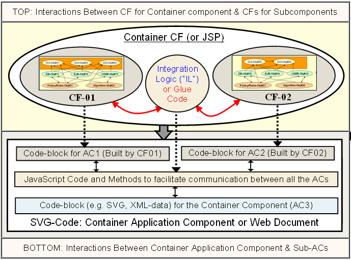
Then implement CF for each container-AC. The container-CF uses one or more CFs,
each generates code-blocks for a sub-ACs at run-time. The container-CF composes
these code-block for sub-ACs to custom generate code for the container-AC. |
Figure#4
|
If the sub-ACs need to collaborate or communicate with each other, then the CF for the container-AC
generates code to loosely couple the sub-ACs. The Loosely coupled ACs communicate by requesting each other’s services. Usually this coupling code for each component
(i.e. AC) is no more than 1 to 9 lines. Each component can be removed or replaced by modifying the few lines of “loosely coupling” code. Therefore it is called “loosely coupled” component. Any loosely coupled component can be removed or replaced in minutes (using its
"unified
handler", which is explained later).
|
Figure#5
Figure#6a
Figure#6b (Detailed diagram for Fig.5 & Fig.6a)
|
The container-CF contains simple code called integration-logic (that runs at server and generate communication code), which loosely couples the service providers and the service-consumers in the application code (i.e. in webpage as shown in the lower part of Fig. 6B). On average each component needs 5 lines of coupling code. One may replace each component by modifying its coupling code. Each Sub-CF encapsulates tightly-coupled objects in an easily replaceable container (click here to learn how it eliminates over 90% of the spaghetti code - Very Important Link). |
Figure#7
|
The container-CF created above can be used again by yet another CF to build one
of its sub-ACs. This process can be repeated to build larger and larger components and finally the application. The following figure shows the chain of dependencies. |
Figure#8
Figure#9
|
Note: This process is not that much different from the manufacturing process to manufactured products such as cars, jetfighters and computers For example, the computers are build by loosely coupling components such as Hard-drive, CD-drive, Network card and Graphics card; where these components in turn build by "loosely coupling" their subcomponents and so on.
It is extremely important that the process is
highly intuitive and repeatable, because, large applications contain large
components, which end up very complex. For example, Jet engines and CD-Drive
are in turn build by assembling loosely coupled components. |
Figure#10
|
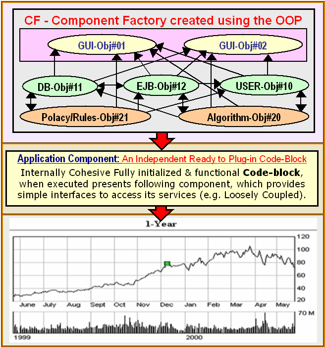
The Object Oriented paradigm tightly couples the Objects. This tight coupling is not avoidable to build some basic components.
The GUI Widgets require several lines of code to initialize with data and
customize them as per user profile. The data is obtained from many data Objects
and by running algorithms and/or based on user specific policies. Therefore the basic CF’s are built by tightly coupling the Objects as shown in the first figure,
which is shown again below:
|
Figure#11
|
Now lets see where the OOP differs from the “Loosely Coupled” process. The OOP do not have a Loosely coupled component concept. The building blocks of the OOP are Objects, where as the building blocks for the Component Based Software Development (“CBSDF”) are loosely coupled
components. Once the component is manufactured and placed in a webpage as shown above, other components
interact with this component through its simple loosely-coupled service oriented interfaces as shown below: |
Figure#12

|
Listing#1: Sample Code to assemble any two replaceable components |
|
|
In the OOP, a new functional component is added to the application by adding
several new Objects by referring them in existing files as shown below. If two components need to collaborate, some of the Objects of first component are coupled with some of the Objects of the second component.
This in effect results in tight coupling between both
the components. This makes it hard to track or document the dependencies between the components (For example, if one wishes to remove or replaces a component).
|
Figure#13
|
On the other hand the CBSDF can maintain the physical-separation and independence of each of the 'loosely coupled' component forever. The Objects never interact across the component boundary. The components collaborate by requesting each other’s services through “loosely coupled” service interfaces. Therefore it is possible to refine each component independently by refining the CF. If required, the component can be remove or replace in minutes by severing its loose-couplings. |
Figure#14

|
In the OOP: More objects are added to the application to add third AC as
shown below. The Object interaction crisscrosses
across many files and of course the non-existing component
boundaries.
This in effect
“tightly couples”
all the Objects of
all the ACs. It is nearly impossible to predict what soft of effect, even a
small change to an Object, would have on the other parts of the application.
If future developers, needs to replace/remove a large component, isn't it very
complex to find which set of Objects need to be removed and how to resolve dependencies of other Objects on this set of
Objects? If Object interaction cannot be contained with in physical
boundaries, doesn't it create
complex tangled “irrational dependencies” between even non-interacting
Objects (for example, by virtue of being referred to in the same source
files). |
Figure#15

Figure#16
|
The figures above and below contain three components & clearly illustrates the difference between the OOP and CBSDF |
|
The CBSDF in effect encapsulates the messy "component manufacturing" process, which needs many lines of code to tightly couple the Objects in a "CF" (a Replaceable-container) and exposes simple "loosely coupled" service interfaces. The Object interactions with in the boundaries of the component is unavoidable and, of course, serve very useful purpose. But, Absolutely there is no need for the Object interactions to cross the component boundaries, which causes the spread of tangled web of spaghetti code and Irrational Dependencies. |
Figure#17
|
The above figures uses server side "integration logic" to facilitate communication between the
ACs.
Alternative techniques may be employed, such as "Service Oriented Architecture" to
get services or to communicate with each other.
|
Figure#18
 |
|
Publish and subscribe method to locate services |
|
These
Object dependencies may not be a big deal,
If a software application has only three components. But some applications have hierarchies of hundreds or even thousands of components. Each of them must be independently updated
or replaced to meet the evolving needs. It require us to build larger and larger high-level
"plug-n-play" abstractions, which must be
loosely coupled to be independent. |
|
Figure#19 | |
|
|
|
|
Left Side: Supply chain for the components |
Right Side: The Product |
|
Important Note: To understand the the CBSDF please always keep in mind that the left side is just factories to generate 'code blocks' for custom 'parts'. The resultant webpage in the right side is the 'real application'. Due to historic reasons, we may be calling it webpage. But it could contain millions of lines and complex 2D/3D GUI components. The resultant application can be far more complex than one could possible build for any existing platforms such as Windows/VC++ or Java today. | |
|
For example, a complex component such as CF#15 (or CF#20, CF#07) can be removed in minutes by changing about 5 lines code that loosely binds it. Please see how CBSDF provides a "unified handle" for each component. But, in the OOP such complex components require painstakingly chipping away hundreds of tightly coupled Objects in dozens of files, which makes it nearly impossible to remove. Imagine the complexity of removing a large component that contains the AC-20 (of CF#20) and ten other such ACs. The following figure shows the component interaction in an application. |
Figure#20
|
The CBSDF is highly scalable and repeatable and has no limitations. In fact CBSDF offers extra dimension of freedom and flexibility to build highly custom and complex GUI application than possible
before on the traditional GUI platforms (e.g. Java/Swing or Windows/VC++).
Imagine the excellent control one has, since he can constantly fine tune each
CF on the left side independently, with little concern of breaking the
application on the right side. This web site proves that the “loosely Coupled” paradigm can be used to build any online graphics intensive
component. |
|
SUMMARY: The CBSDF controls the complexity by distributing the complexity among many 'loosely coupled' independent building blocks:
|
|
For example, one simple development process can be: set up a simple supply chain of "Component factories" as shown in the left side. Then independently fine tune each CF until one gets desired functionality for each component (and the resultant application). This
process can be continued during maintenance cycles to adopt the application to
evolving needs (no pesky irrational tangled Object level dependencies). This
is not different from design upgrades of parts in future release models of
cars or computers. If
one doesn't like a large subsystem (e.g. AC-19), it takes few minutes to
replace its CF (once he creates a new replacement CF by setting up its supply chain and refine the
functionality of its subcomponents until satisfied with the new AC). |
|
Observations on the practice of Software Engineering About 80% of software engineering deals with changing existing software It is not the strongest of the species that survive, nor the most intelligent, but the ones most responsive to change -- Charles Darwin Time to market is an important competitive advantage: incorporate successful innovations quickly |
Copyright (C)
2006 Pioneer-soft LLC. All rights Reserved